

Managing Ready-to-Use (RTU) Containers in Aseptic Production Facilities A Path to Efficiency and Compliance
[Author's Note: The Alliance for RTU is an expert platform with a mission to advance the industry's transition to high-quality, sterile primary packaging, thereby enhancing operational efficiency and patient safety. It collaborates with key industry stakeholders, such as IMA Life – a leading player in aseptic processing and freeze-drying solutions- to provide relevant insights to pharmaceutical professionals. In this article, they jointly illustrate how to streamline RTU container integration in aseptic fill-and-finish lines, combining automation and packaging expertise.]
The growing adoption of ready-to-use (RTU) containers is reshaping aseptic pharmaceutical manufacturing. By eliminating in-house sterilization and simplifying material flow, RTU systems have evolved from niche applications to mainstays of high-speed, large-scale production. Yet as manufacturers embrace these presterilized formats, they face new challenges in logistics, facility design, and contamination control—demanding a careful balance between efficiency, flexibility, and regulatory compliance.
High-Speed Scenario and Subsequent Challenges
In the past, aseptic filling lines for sterile parenteral drugs relied on bulk processing. Large quantities of vials, syringes and cartridges arrived unpackaged and required in-house washing, sterilization and depyrogenation before filling in aseptic conditions. The introduction of ready-to-use (RTU) containers, starting with prefilled syringes (PFS) in the 1980s and expanding to vials and cartridges in the early 2010s, marked a significant shift. These presterilized containers, packaged to maintain sterility up to the filling line, eliminated the need for in-house sterilization, reduced manual handling and simplified operations. RTU suppliers providing sterilized containers are responsible for the validation of the sterilization cycles utilized, offering major benefits to manufacturers.
Removing the sterilization step has increasingly been adopted, especially in the PFS sector and flexible lines used by CMOs/CDMOs, to meet varying market demands. What began as a solution for small batches has evolved into a scalable option for high-speed production, enabling long-duration campaigns with multiple batches in large fill–finish plants. This shift has introduced new logistical and operational challenges, particularly in facilities still reliant on traditional processes.
High-productivity facilities handle a range of injectables, such as small molecules, antibiotics, PFS vaccines, insulin, biologics like monoclonal antibodies and blood-derived products. These facilities often process 1,000–2,000 litres per batch across several tanks, serving fillers that produce 24,000–36,000 units per hour. Multibatch campaigns can produce over one million doses, with annual outputs between 100 and 200 million units, representing the cutting edge of injectable production.
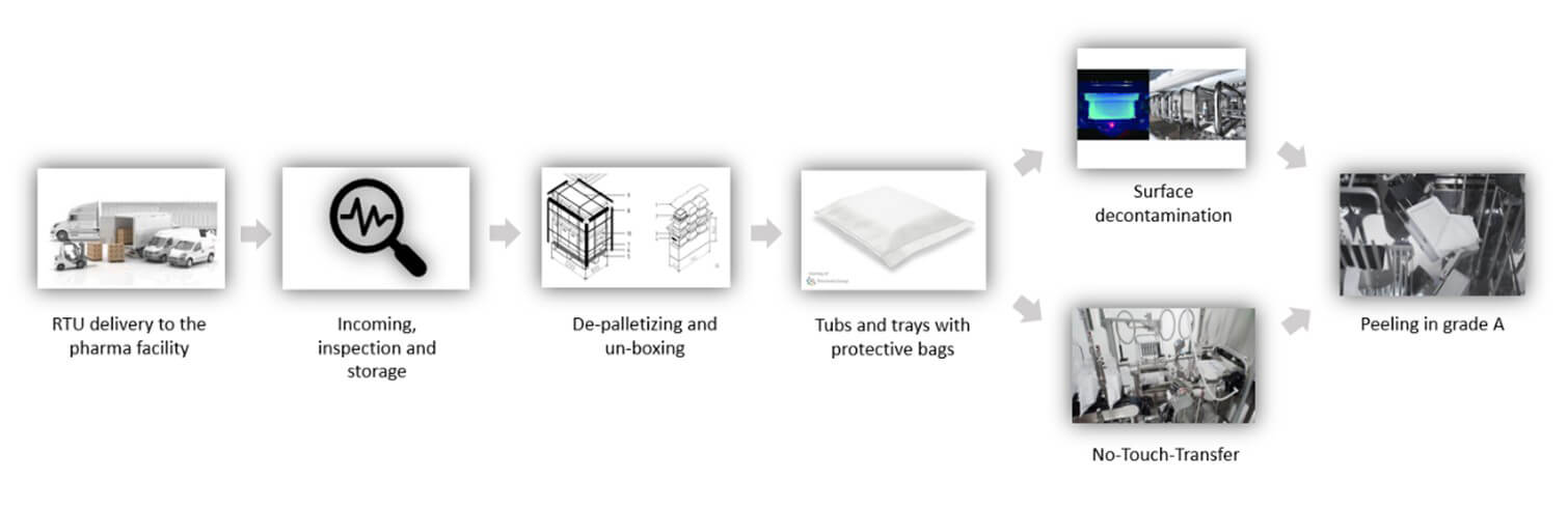
Such scale demands efficient tub-packaging logistics. For instance, a batch of 200,000–300,000 PFS units requires 2,000–3,000 tubs (assuming 100 syringes per tub). Over multiweek campaigns, logistics must manage up to 20,000 tubs, posing storage and handling challenges. Introducing RTU packaging into aseptic facilities involves multiple steps, each influenced by the sterility assurance strategy, cleanroom configuration and level of automation. A thorough analysis requires breaking down each phase of the tub- or tray-handling process, assessing variations and available alternatives (see Figure 1).
From Delivery to Depalletizing and Unboxing
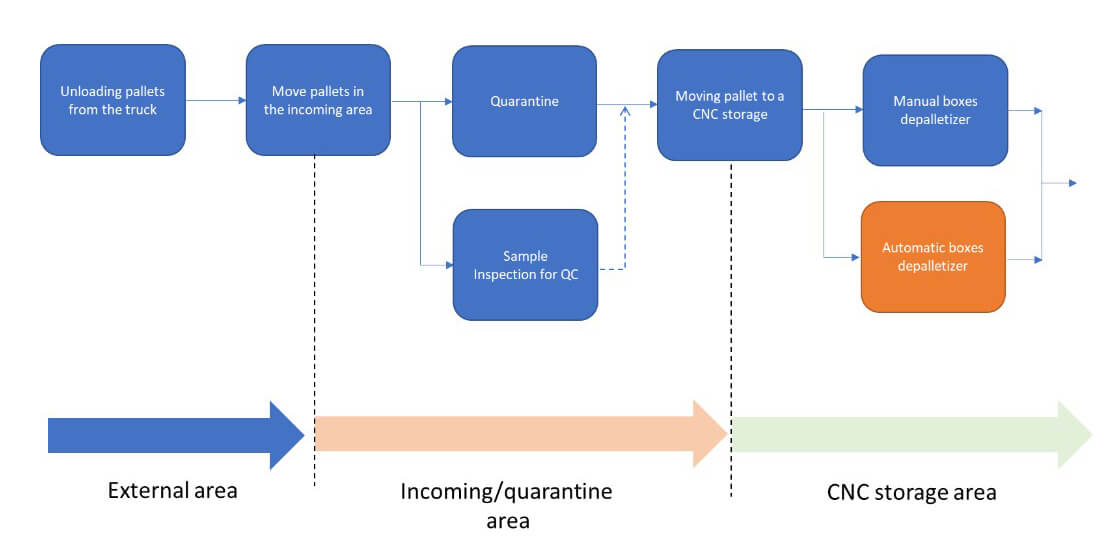
The flowchart in Figure 2 illustrates the individual steps from delivery to depalletizing. The starting point is the arrival of the pallet at the external unloading area of the production site, carrying a defined number of tubs in accordance with supplier specifications and, if applicable, customer requirements.
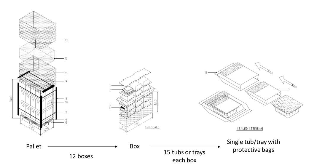
The workflow begins with the arrival of the pallet at the external unloading area, carrying tubs arranged per supplier specifications. Standard pallets, like those from a specific supplier, typically hold 12 boxes (four per layer), each containing 15 upside-down tubs in rows of three, sealed in protective bags (see Figure 3).
Upon arrival, materials undergo incoming inspection, including document and certificate checks, visual inspection, dimension verification, sterility testing and, if needed, specialised analyses (e.g., infrared spectrum, silicone extraction). Some controls may be delegated to the supplier, with results documented and shipped with the goods. Materials are held in quarantine until verified and then moved to compliant storage. The tests and incoming verification strategy can be defined between the RTU supplier and the end customer.
A typical production batch may require storage for 10–20 pallets, with up to 100 pallets entering weekly during full campaigns. Efficient depalletizing is essential, especially as pallets cannot enter classified areas due to contamination risks and handling constraints. Steel or plastic pallets are sometimes used instead of wood for easier cleaning. Before entry into classified zones, shrink wrap and supports are removed, and boxes are depalletized outside these areas. This process ensures compliance with cleanliness standards while maintaining efficient material flow.
From Unboxing to Singularized Tubs and Trays with their Protective Bags
Once removed from the pallet, the individual box can be transferred into a classified environment (see Figure 4).
After depalletizing, each box is transferred into a classified area via material airlocks (MAL) to reduce contamination (see Figure 5). Boxes are cleaned with isopropyl alcohol and biocides. Inside, RTU containers are sealed in plastic tubs protected by single or double bags. These layers maintain sterility and low bioburden.
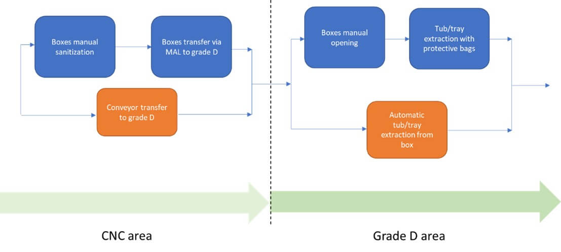
As packaging is removed, while approaching higher classified cleanrooms, careful handling is essential to avoid damage. A visual inspection is recommended to check bag integrity and ensure no transport damage. Any breach may compromise sterility, preventing safe transfer into the Grade A isolator or RABS environment.
Layout Strategies
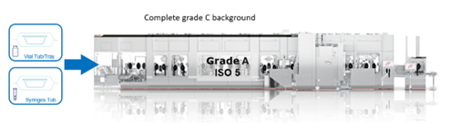
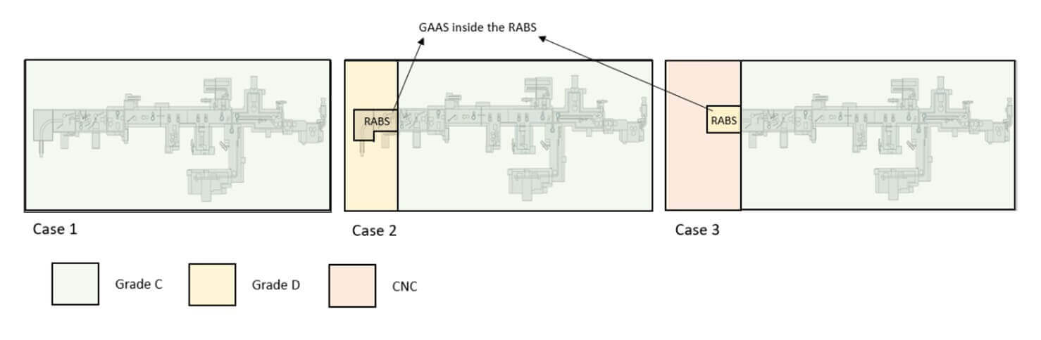
In defining the facility layout, different approaches are possible, each with significant impacts on the overall footprint of the production area. The first approach (Case 1) involves installing the filling equipment, including areas where the automatic or manual bag-removal process takes place entirely within Grade C. Since regulatory requirements stipulate that an open isolator (equipped with mouse holes protected by a pressure cascade) must be installed in Grade C, one solution is to have the fill–finish line, including debagging chambers, within the Grade C cleanroom (see Figure 6).
Alternatively, it is possible to maintain only the “aseptic core,” the Grade A-isolated area where the aseptic process occurs, in Grade C background, while positioning the initial debagging phases or the line introduction point in Grade D (Case 2).
fill-finish-isolated-line-installed-between-grade-d-and-grade-c-cleanroom.jpg?sfvrsn=3bc32f64_1)
-fill-finish-isolated-line-installed-between-grade-d-and-grade-c-cleanroom.jpg?sfvrsn=67a97bf6_1)
Introducing RTU packaging from Grade C (Case 1) could have these advantages:
- Higher sterility assurance in RTU packaging manipulation: Grade C provides a cleaner environment, lowering the risk of contamination for bag-protected tubs/trays during initial handling stages.
- Minimized risk in grade transition: Introducing protected tubs/trays in Grade C reduces the potential for particles or contaminants to manage containers as they move into higher-grade areas.
Introducing RTU packaging from Grade D (Case 2) could have these advantages:
- Reduced facility costs: Grade D areas require less stringent environmental controls than Grade C, leading to lower construction and operative costs versus a “full Grade C” configuration.
- Enhanced logistical flexibility: The use of Grade D for initial handling stages can facilitate the transfer of tubs or trays, skipping the requirement of a transfer using MALs between cleanrooms. Moreover, Grade D areas are often more accessible and allow for easier material flow and operator gowning.
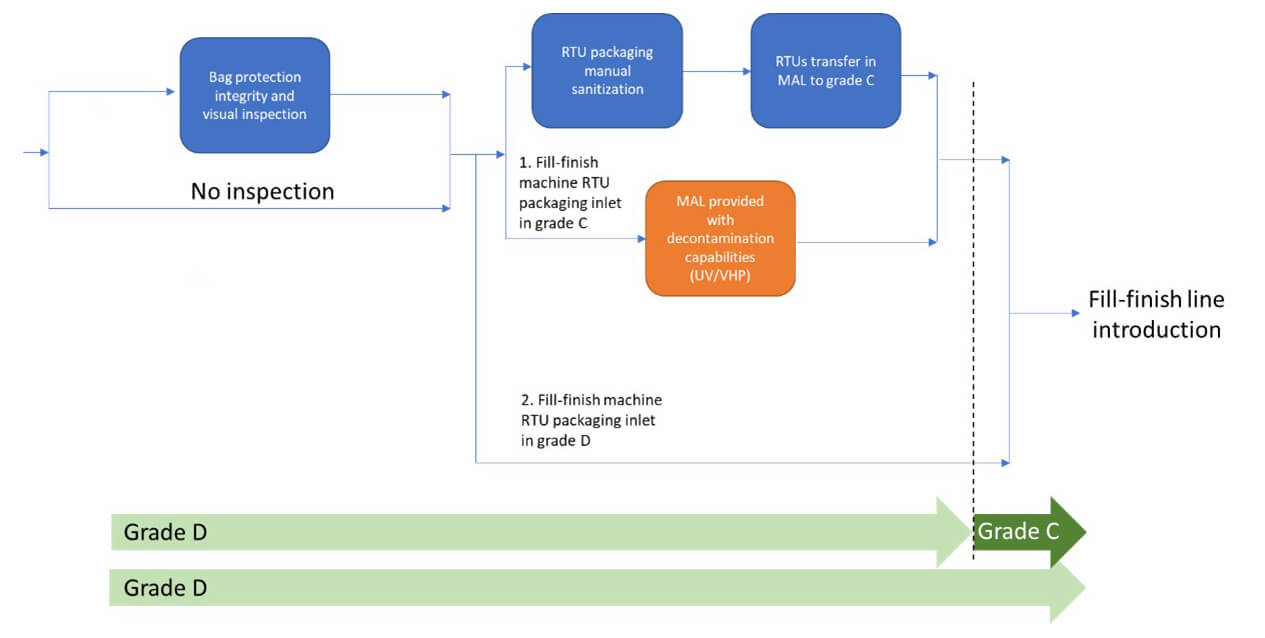
The facility layout and associated cleanroom class transitions are influenced by the chosen method for transferring tubs and trays into Grade A (see Figure 8). Whether using a no-touch-transfer (NTT) system or a decontamination process affects the classification needs of the RTU-packaging entry area. When a RABS is used with a controlled nonclassified (CNC) or Grade D background, specific procedures, contamination risk analysis and environmental monitoring are required to prove how RABS can mitigate risks compared to a low-grade cleanroom.
At some sites, the strategy eliminates the need for a Grade D area entirely, starting the tub or tray transfer directly from a CNC area (Case 3). In this setup, tubs are moved from CNC into Grade C via a RABS, which serves as a controlled transfer zone where sanitization is performed. In this case, the RABS is positioned to align with airflow from the Grade C room, creating a protective barrier that limits CNC air infiltration.
Debagging and Final Introduction into Grade A
There are two primary methods for introducing RTU packaging into an isolator while ensuring the sterility of the Grade A environment and preserving the sterility assurance of the containers.
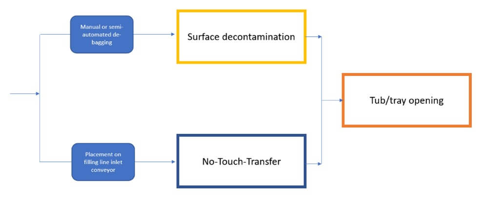
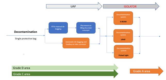
- Surface decontamination: This method reduces bioburden on the outer surfaces of tubs or trays before entry into the aseptic area. Automated systems using high-concentration vaporized hydrogen peroxide (VPHP), electron beam, or ultraviolet (UV) pulsed light effectively decontaminate surfaces, helping prevent contamination in critical zones.
There are different types of surface-decontamination technologies, the most common among them being:
- Vapor hydrogen peroxide (VHP) decontamination using large/small transfer chamber
- Pulsed-light decontamination
- Electron-beam (e-beam) decontamination
- VHP decontamination using high-speed continuous tunnel
From the perspective of NTT systems, there are solutions with different degrees of automation:
- Completely manual solution, where the operation is performed entirely by operators in the cleanroom.
- Semi-automatic solution, where debagging and introduction operations are assisted by an automation system, but still managed by an operator, especially in the bag pre-stretching phase.
- Automatic or “robotized” solution, where debagging and introduction operations are entirely delegated to automatic or robotic solutions.
These current technologies are characterised by their own advantages and disadvantages.
No-Touch-Transfer Approach
A NTT approach (see Figure 10) for opening a bag-protected tub or tray is designed to maintain sterility and minimize contamination risks by avoiding direct human contact with the primary container.
Here’s how a typical NTT process unfolds (see Figure 11):
- Material Transfer to RABS/Isolator: Double-bagged tubs or trays are brought to the isolator or RABS entry, typically via an automated conveyor or pass-through system.
- Outer-Bag Removal: In a Grade C area with Grade A Air Supply protection, the outer bag is removed. The inner-bag-protected container is pushed into a Grade B or Grade C zone using a no-touch method. Precise positioning, protective airflow and transfer through the mouse hole without direct contact are key elements of the no-touch approach.
The NTT process can be implemented through various automated solutions, either with partial operator assistance or as a fully automated system. In high-speed environments with cycle times of 12–15 seconds, full automation is recommended to prevent bottlenecks caused by operator intervention. Manual implementation of NTT is challenging and limited by strict cycle times. In such cases, glove use and fast handling rates (5–6 tubs per minute) make it difficult to meet low particle-contamination requirements, as illustrated in Figure 12.
-ima-life-ntt-implementation-supported-by-robotics.jpg?sfvrsn=76e61ebe_1)
-ima-life-ntt-implementation-supported-by-robotics.jpg?sfvrsn=e0e7c81e_1)
The barriers used to protect the debagging process can also have different configurations. First, the process can be performed in various background environments, requiring greater attention to, at least, RABS solutions when the tub or tray introduction process occurs in Grade D. At the same time, NTT design involves maintaining a pressure differential between the downstream chamber (with higher classification) and the upstream chamber (with lower classification). This pressure differential creates the critical protective local airflow needed to prevent contamination from the dirtier environment in the lower-classified chamber.
The main requirement of NTT systems is that of maintaining the sterility of primary packaging. Unsealing (peeling) tubs or trays must occur in a Grade A environment, with the sterility of the inner bag being critical to avoid contamination. Packaging types, such as single-bag, double-bag or vacuum-sealed (which poses challenges for NTT), may affect the design and performance of automation systems. While automation improves sterility assurance, it also adds complexity to production line layout. RTU suppliers are responsible for ensuring packaging sterility, including the inner bag.
Key NTT considerations include RTU site sterility and transport safety. Production sites must understand packaging materials, qualify suppliers and assess sterilization validations. During transport, packaging integrity must be preserved through controlled logistics. Suppliers should conduct shipping studies to confirm packaging performance during transit. Upon arrival, integrity checks, visual inspection and routine quality controls on tubs and trays are essential.
The use of anthropomorphic robots in the introduction process with NTT (see Figure 13) is advantageous from the standpoint of container transport; it occurs without belt systems or contact-drag mechanisms, thereby minimizing contamination in access areas to Grade A. Thanks to the flexibility of robotic handling and the specific design of the docking system, the NTT process can be strengthened in various aspects:

- Protective airflow on the docking station controlled with an automatic shutter, synchronized with the robotic-assisted bag-opening
- Internal part of the tub is never in direct or indirect contact with the low-classified chamber
- Tub remains protected during the cutting phase—cutting takes place away from the mouse-hole area
- Tubs/trays remain sealed during the entire process—the tub/tray is placed closed in front of the protective flow of the mouse hole
- Process is easily adapted to different types of packaging and bags
Surface Decontamination Approach
Surface decontamination for introducing materials into Grade A aseptic environments is a standard method used in transfer chambers for isolators and cleanrooms. This approach is widely accepted and proven in the pharmaceutical industry. However, opportunities for optimization lie in the choice of technology to reduce microbial load. Currently, three main strategies are used: VHP, UV or pulsed light, and ionizing radiation (e-beam).
In this strategy, tubs are introduced after bag removal, allowing RTU packaging to be simplified to a single protective layer (Figure 14). This reduces the complexity of the debagging phase, which can be done with less precision and in a lower-grade (D) environment, unlike the stricter NTT protocols.
In contrast to the packaging simplification, other technological challenges emerge that introduce a series of risks that must necessarily be analysed and assessed to properly manage surface decontamination methods:
- Ability to ensure the required productivity (tubs/min)
- Absence of residues following the decontamination process that could in any way compromise the stability of the drug in the primary container
- Assurance of a requested logarithmic reduction, which can align with the traditional 6-log reduction typical of a decontamination process or be set to a lower log-level, such as 4-log, if the low bioburden of exposed surfaces can be demonstrated
VPHP decontamination, using a high-speed continuous tunnel, is a new technology recently made available (see Figure 15). The primary objective was to replicate the strategic advantages of an e-beam tunnel by utilizing traditional hydrogen peroxide-based decontamination methods. IMA LIFE has successfully adapted an existing technology from food processing, where high-concentration VPHP exceeding 8,000 PPM is used. By optimizing the combination of temperature, high concentration and airflow distribution, it becomes feasible to achieve the 6-log decontamination time in approximately 30 seconds.
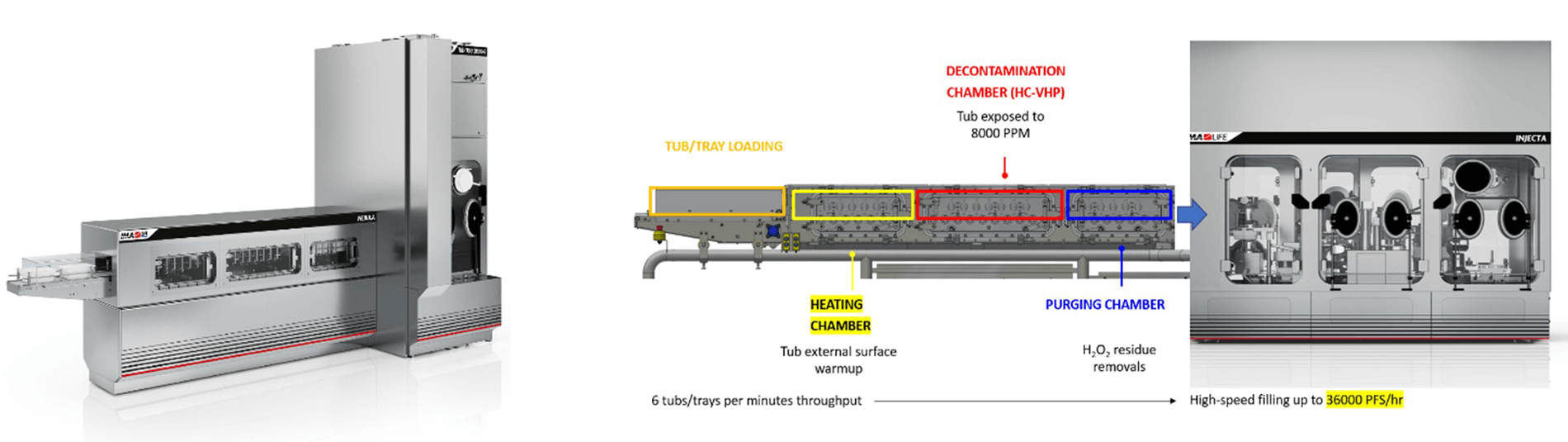
The process is divided into three chambers maintained at different pressures to achieve dynamic segregation of the VPHP within the machine and allowing for an “open” process without a physical airtight separation between the decontaminated area and the external cleanroom environment. This approach enables continuous operation of the decontamination tunnel where the RTU packaging passes through the three chambers moved by a simple roller-based conveyor system.
Surface Decontamination: Residues Challenge
Managing oxidant residues is a key challenge in decontamination methods, especially due to their potential impact on sensitive pharmaceuticals. Residues can result from VHP (H₂O₂) or high-energy processes like e-beam, which generate radicals and ozone. While effective for surface decontamination, these methods may leave reactive traces, even at parts per billion (ppb), that can degrade sensitive compounds.
Both continuous and batch decontamination strategies may lead to trace H₂O₂ inside primary packaging, affecting both product stability and shelf life. Residue studies using sensitive methods like “Red Amplex” or “Vacu-vials” detect low H₂O₂ levels via a redox-sensitive dye. Liquid samples from primary containers are mixed with the reagent and assessed visually or with a spectrophotometer, detecting levels below 100 ppb, ideal for sensitive sterile pharmaceutical drug products.
Similarly, e-beam systems may cause slight oxidation through radicals and ozone, impacting certain formulations. Evaluating packaging material compatibility with the RTU supplier and adjusting the beam strength and exposure time to reduce these effects is crucial. In summary, while H₂O₂ and e-beam methods are effective, their potential to leave reactive residues requires careful process design, validated packaging and ongoing monitoring to ensure product quality and microbial safety.
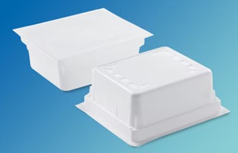
The development of new types of secondary packaging is leading to the release of products on the market that can minimize the penetration of oxidants into the packaging during decontamination phases (see Figure 16). Preliminary tests using the NEBULA system have shown that a new packaging technology can strongly reduce the risk of VHP penetration. This feature allows for a reduction in the time and complexity of the desorption process needed to bring residual levels below the 100 PPB required for sensitive pharmaceutical products.
Decontamination vs. No-Touch-Transfer
The choice of introduction strategy is a crucial factor in managing RTU containers. Comparing the main strategies reveals the following:
- Layout Impact: NTT systems require multiple isolated or RABS zones and robotic automation for high-speed debagging, needing more space than e-beam or tunnel-based decontamination systems.
- Packaging Flexibility: NTT solutions demand precise robotic handling, especially of the inner bag, which may behave unpredictably at high speeds (5–6 tubs per minute), risking jams. E-beam or VHP tunnels simplify this by removing bags beforehand and transporting tubs on rollers. While e-beam shielding movements can cause occasional issues, there are generally fewer than in fully robotic NTT systems.
- Sustainability: Decontamination systems support single-bag solutions, reducing waste and packaging costs. NTT generally requires double-bag packaging to meet regulatory standards, increasing waste and cost.
- Operator Needs: Manual or semiautomatic NTT systems require skilled operators to keep pace with production, working through glove ports and adjusting packaging. Fully automated systems reduce operator involvement to simple loading. Decontamination lines allow for easier manual debagging before machine insertion. Only full automation ensures minimal operator demand, while semimanual solutions are less suited to large-scale output.
- Oxidizing Residue Risk: NTT and pulsed light methods avoid the use of gas or ionizing sources, eliminating oxidizing residue risks. Surface decontamination, by contrast, requires strict evaluation to manage this risk.
- Maintenance: Robotic systems benefit from using standard, replaceable robots, reducing inventory needs. However, they require specialized software skills, possibly requiring training investments. Decontamination technologies (e.g., pulsed light, e-beam) suffer wear and need regular replacement, with some models incurring recurring costs. VPHP systems, like those in isolators, are low maintenance if used with validated H₂O₂ solutions (see Figure 17).
Conclusions
The revolution in the use of RTU containers for high-speed aseptic filling lines is transforming the layout of production facilities and the logistical management of materials by combining automation, robotics and processes aimed at reducing microbiological risk. The success of high-speed production in a next-generation plant requires integrating these elements within the production area, from the external entry point to the Grade A aseptic zone. The use of RTU containers strongly facilitates and reduces the efforts to achieve GMP-compliant facilities. Advanced solutions and optimization suggestions, both from suppliers of presterilized materials and from fill–finish equipment providers, can help the production site achieve maximum efficiency and sterility assurance.