Lower the H202 Concentrations in Your Isolator with One Easy Upgrade
In recent years, the number of protein- based biologic drug products has grown. Parallel to this, the use of filling line isolators in biopharmaceutical manufacturing plants has increased. Some of these products are extremely sensitive to oxidation. The majority of aseptic manufacturing isolators are decontaminated with H2O2, so potential oxidation of these sensitive products has become a concern (1). Although this concern has mainly been associated with isolators, there is also oxidation risk to drug products filled in traditional cleanrooms due to the use of oxidative liquid chemical agents for wipe downs and mopping. Residual vapors from sodium hypochlorite (bleach), a commonly used cleanroom sanitizing agent, have been found to cause oxidation in proteins more quickly when compared to hydrogen peroxide/peracetic acid mixtures (2).
A study was conducted on a syringe filling line to benchmark the residual concentration of vapor phase hydrogen peroxide (VPHP) in an isolator after the existing aeration process was completed using a Picarro G1114 Cavity Ringdown Spectrophotometer (CRDS) with a VPHP measurement range of 100 ppm to 0.1 ppm. The programmed aeration phases totaled approximately four hours and 33 minutes, at which point all of the built-in electrochemical cell sensors were measuring ≤ 1.0 ppm H2O2. Measurements with the Picarro instrument were taken at three locations, representing areas where the drug product would be directly or indirectly exposed to oxidation. An area near the stopper bowl was selected because of the potential for stoppers to absorb H2O2, which results in an indirect exposure to the product. Areas in the filling location and in the N2 gas overlay station were sampled because these are places where liquid drug products are still exposed to the aseptic environment. Air samples were taken using polytetrafluoro- ethylene (PTFE) tubing positioned at the three locations using the built-in sampling pump in the Picarro unit. The isolator was fully loaded with the supplies that would normally be required for a production run. Approximately six hours after aeration began, the Picarro measurements ranged from 0.328–0.494 ppm H2O2 in the three locations.
Catalytic Converter Upgrade
After six hours, the residual H2O2 concentration inside was considered to be too high for many oxidation-sensitive products. The acceptable limit for H2O2 concentration inside an isolator during a filling process depends on many factors, including line speed, vial, or syringe size, allowable line stoppage time before triggering a line clearance and, ultimately, the oxidation sensitivity of the drug product itself. While there are many factors to be considered, a concentration limit of 0.050 ppm H2O2 (50 ppb) has been used as a target for many recent projects. A project was initiated to upgrade the isolator so it would be able to reach low levels, such as 0.050 ppm H2O2, in a reasonable amount of time.
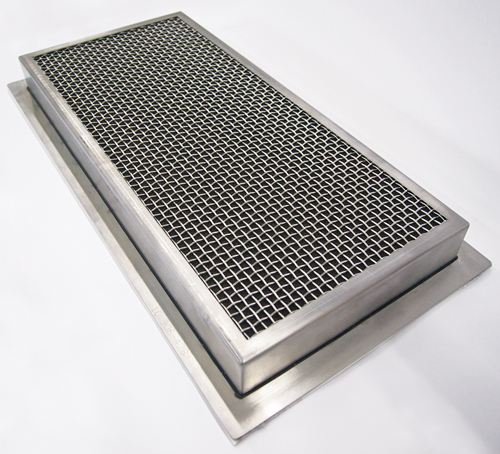
In most isolators, the fresh air supply rate is the main factor affecting aeration. The fresh air dilutes the outgassing hydrogen peroxide until the desired low-level concentration is reached. Using single-pass decontamination piping allowed for catalytic panels to be inserted above the recirculation HEPA filters without compromising the decontamination process. The catalytic material is a porous 316L stainless steel substrate coated with proprietary metallic oxides. Panels are constructed with a stainless steel frame and wire mesh to contain the catalytic substrate. A typical catalytic panel is shown in Figure 1. The panels are made in the same rectangular shapes as the recirculation HEPA filters in the isolator.
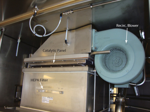
This way they can be slipped above them and fastened with existing hardware. No other mechanical modifications to the isolator are required. A typical catalytic panel installation is shown in Figure 2.
The recirculation blowers are not turned on during the decontamination process. During the aeration process and normal operation, these blowers are turned on and recirculate a substantial amount of air through the working space of the isolator to provide the unidirectional air flow (UAF) required for an aseptic filling system. The catalytic panels in the recirculation loops destroy a significant amount of the VPHP residue while, at the same time, reducing the concentration via dilution from the fresh air exchange.
The syringe filling isolator has five recirculation blowers that provide the large amount of airflow required to provide the UAF in the working area. The isolator was upgraded by installing catalytic panels between the re- circulation blowers and the terminal HEPA filters. The volume of air recirculating within the isolator is much higher than the fresh air supply. For example, the isolator in question has a total volume of 16.3 cubic meters (m3) and a maximum fresh air supply of 3,100 m3/hour, which yields an air exchange rate of 190 air exchanges per hour. The UAF volume can be calculated based on the 5.9 square meter footprint of the isolator’s recirculation unit and the UAF set point of 0.45 m/sec used during aeration, which yields an airflow rate of 9558 m3/hour. Based on the total volume, the UAF airflow produces an exchange rate of 586 air exchanges per hour (3). The UAF air flow passes through the catalytic panels, so it decreases the concentration of the VPHP during aeration more quickly than the isolator could prior to the upgrade.
Residual Levels Before and After Upgrade
After the system was upgraded with catalytic converters, a study was conducted to measure the H2O2 residual concentration during and after aeration when the system was switched to production mode. Residual H2O2 concentration data from the three locations taken before and after the catalytic converter upgrade are shown in Figures 3–5. The H2O2 injection phases for these cycles lasted 2:15 (h:min). The isolator is heated during the first 3:33 (h:min) of aeration. By the end of the heated phase the air temperature within the isolator is approximately 40 ºC. The warm temperature increases the outgassing rate of the H2O2 residue, which causes relatively high concentration measurements during this phase. During the next hour of aeration, the temperature set point changes to the production set point of 21ºC. The cooler temperature slows the outgassing of the H2O2 residue causing the mea- surement to drop to ≤ 1.0 ppm before the catalytic converter upgrade, and to much lower levels after the upgrade by the time the 4:33 (h:min) Aeration phase is complete. Concentration measurements continued after Aeration was completed and the isolator was switched to production mode.
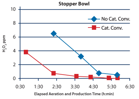
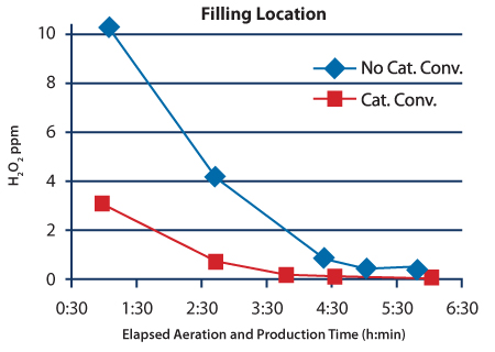
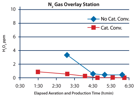
The concentration data shown in Figures 3–5 clearly show that the catalytic converter upgrade improved the performance of the process during the initial stages of aeration. The catalytic converter upgrade reduced the residual H2O2 concentration by more than tenfold in the samples taken near the stopper bowl and nitrogen gas overlay station at the six-hour mark. The reduction in the filling location was also substantial: the H2O2 concentration measure dropped from 0.328 ppm to 0.058 ppm after the upgrade.
Conclusion
The catalytic converter upgrade of the isolator enabled the syringe filler to be used to fill oxidation-sensitive products without enduring extremely long hold times after the end of the decontamination process. Reducing the hold-time decreases costs and saves energy. The data from the three locations shows that residual H2O2 concentration varies within the isolator. It is important to consider various locations along the path of the filling line when making risk assessments regarding exposure of sensitive drug products to oxidizing agents.
References
- Yin, F., Vance, E.A., Kovach, P.M., Troyer, G., and Grothen, C. “Compatibility Study of Vapor-Phase Hydrogen Peroxide (VPHP) and Biotech Products in Isolators.” Presented at the ISPE Washington Conference, June 2007.
- Wang, W., Cui, T-Y, Wang, J., and Martin-Moe, S., “Oxidation of Protein by Vaporized Sanitizing Agents,” PDA Journal of Pharmaceutical Science and Technology 58 (2004): 121–129.
- Eddington, E., Lanier, J., Walsh, M., and Kleinmann, S. “Case Study: Implementation of Catalytic Technology to Improve the Aeration Process for a Syringe-Filling Line Isolator.” Pharmaceutical Engineering 36 (2016): 74.


